Imaging and color measurement · Studies
When a uniform field is not radially uniform
Of 52 integrating-sphere captures, only three had enough headroom to measure. Across those three frames, four corner blocks at equal distance from the image center differed by 16.1–20.0% of their average. A field that depends only on radius has to give all four the same value, so one centered radial model cannot describe any of the accepted fields.
The question
A flat-field capture is meant to show how a camera system responds when the incoming field is uniform. If the recorded signal falls smoothly with distance from the image center, a compact radial correction may be enough. If locations at the same radius behave differently, that model is missing a directional term.
This study asks whether a centered radial model describes an archived integrating-sphere capture series. It works on the color-filter-array (CFA) mosaic—the red, two green, and blue sample positions before demosaic—so overall falloff and color-dependent falloff remain separately visible.
Why the archive needed screening first
The retained series came from an earlier course project, not from a dedicated shading-calibration campaign. Fifty-two sphere frames survived across three apertures, along with dark controls, but most exposures placed the bright part of the field near the sensor ceiling.
That is not merely an exposure inconvenience. Clipping flattens the recorded peak, making the field appear more even than it was. A response map made from such a frame would underestimate falloff. The analysis therefore measures headroom separately for all four CFA positions over both the full frame and a centered gate, and rejects the map if either region is too close to the signal-referred ceiling.
Only three frames retained enough headroom. The other 49 remain useful as a screening result—they show why those exposures cannot answer the spatial question—but they are not converted into response maps.
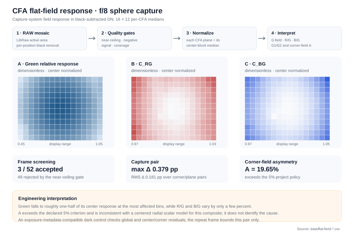
Top: the measurement flow from black-subtracted CFA samples through quality gates, center normalization, and interpretation. Middle: a 16 × 12 green response map and two chromatic-ratio maps. The panels use different display ranges: the large brightness falloff should not be visually equated with the few-percent color-ratio changes. Bottom: the archive screening, matched-pair comparison, and four-corner asymmetry result.
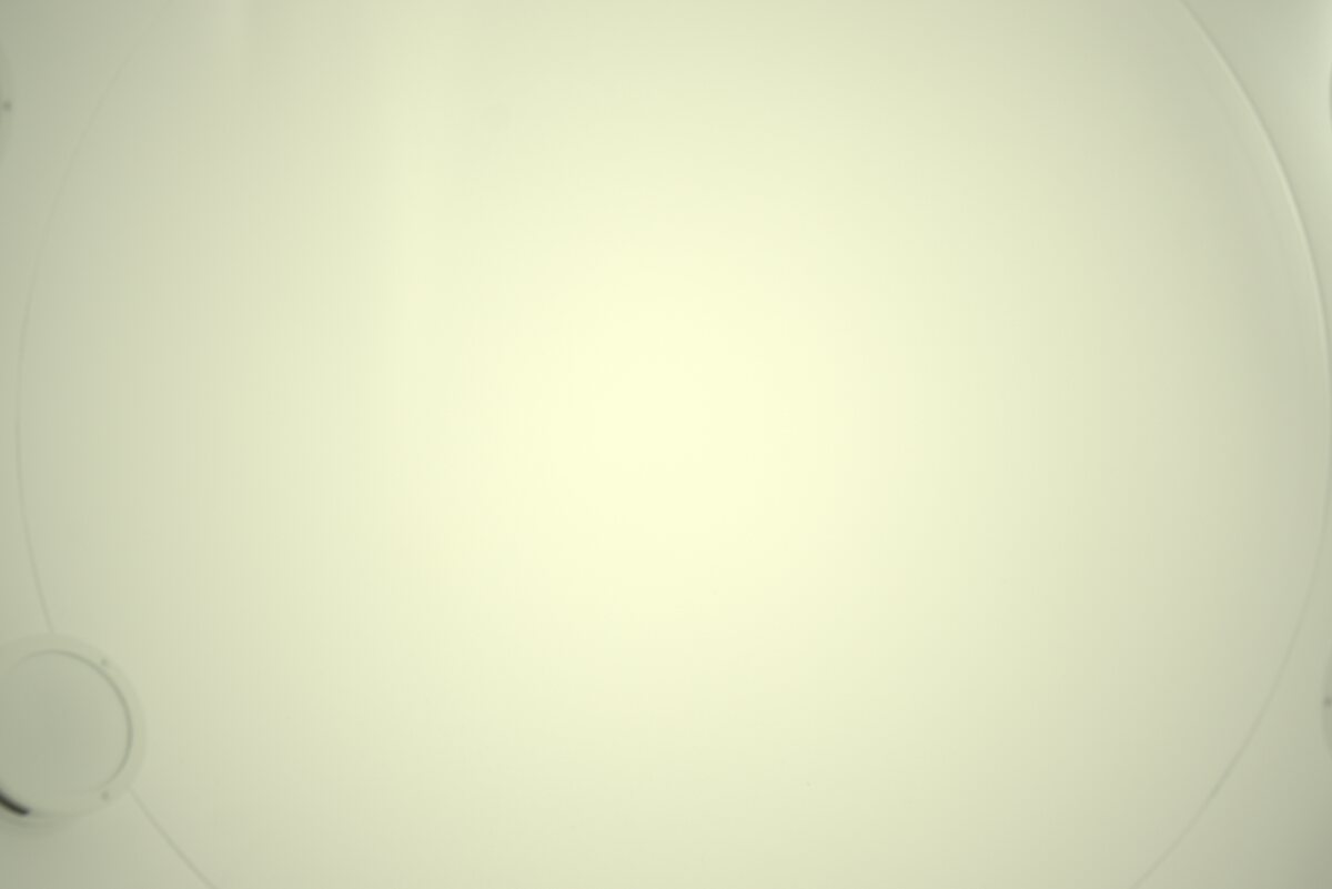
A reduced, metadata-stripped view of the physical capture. It helps explain the setup, but it is not a calibration reference and no result is read from the JPEG; the measurements use the retained sensor mosaic.
What the accepted frames show
For the primary accepted frame, green response ranged from 0.4801 to 1.0005 relative to its center block. The center-normalized color ratios moved much less:
| Map | Minimum | Maximum |
|---|---|---|
| Green relative response | 0.480104 | 1.000534 |
| Red / green response | 0.977316 | 0.999956 |
| Blue / green response | 0.999718 | 1.044729 |
| Green-1 / green-2 response | 0.998943 | 1.002342 |
The main result is not simply that one corner is dark. Four separately measured corner blocks sit at equal distance from the frame center. For a field that depends only on radius, all four must have the same response. Their green values instead produced:
A = (brightest corner - darkest corner) / mean corner = 0.196484
The 19.65% spread exceeds the study’s declared 5% diagnostic policy and is incompatible with a centered radial scalar model for this measured field.
The matched 1/1000 s repeat measured 20.00%. Across the 16 corner-by-CFA comparisons, the two frames differed by at most 0.379 percentage points, with 0.181 pp RMS. A third accepted 1/1600 s frame measured 16.09%. All three support the same model verdict, but the lower third value is why the close agreement of the pair is not presented as a general repeatability estimate.
Reference implementation
The relevant calculation from the public C++ implementation.
std::optional<ShadingGeometry> make_shading_geometry(
    int width, int height, const ShadingOptions& opts) {
  // Use even mosaic dimensions and origins so every region contains the same
  // number of samples from all four CFA positions. Odd requests round inward;
  // the effective rectangles are published with the result.
  // Mirrored corner geometry is exact only on an even mosaic. Rejecting odd
  // dimensions is preferable to publishing an incorrect equal-radius result.
  if ((width & 1) != 0 || (height & 1) != 0) return std::nullopt;

  const int block = opts.corner_block_px & ~1;
  const int inset = (opts.corner_inset_px + 1) & ~1;
  if (block < 2 || inset < 0 ||
      2LL * (static_cast<long long>(inset) + block) > width ||
      2LL * (static_cast<long long>(inset) + block) > height) {
    return std::nullopt;
  }

  const auto gate =
      centered_cfa_balanced_roi(width, height, opts.gate_center_frac);
  if (!gate) return std::nullopt;

  const int center_x = ((width - block) / 2) & ~1;
  const int center_y = ((height - block) / 2) & ~1;
  const int right_x = (width - inset - block) & ~1;
  const int bottom_y = (height - inset - block) & ~1;

  const RoiRect center_requested{center_x, center_y, block, block};
  const std::array<RoiRect, 4> corner_requested = {
      RoiRect{inset, inset, block, block},
      RoiRect{right_x, inset, block, block},
      RoiRect{inset, bottom_y, block, block},
      RoiRect{right_x, bottom_y, block, block}};

  const auto center = cfa_balanced_roi(center_requested, width, height);
  if (!center || !same_rect(*center, center_requested)) {
    return std::nullopt;
  }

  ShadingGeometry geometry;
  geometry.gate = *gate;
  geometry.center = *center;
  for (int q = 0; q < 4; ++q) {
    const auto corner = cfa_balanced_roi(corner_requested[q], width, height);
    if (!corner || !same_rect(*corner, corner_requested[q])) {
      return std::nullopt;
    }
    geometry.corners[q] = *corner;
  }
  if (!contains_rect(geometry.gate, geometry.center)) return std::nullopt;
  for (const RoiRect& corner : geometry.corners) {
    if (overlaps(geometry.center, corner)) return std::nullopt;
  }
  geometry.valid = true;
  return geometry;
}
code/src/shading.cpp · lines 82–136
A negative case that explains the two headroom regions
One f/8, 1/500 s frame measured only 0.4964% near ceiling when averaged over its worst full CFA plane—below the 1% policy—but 11.6319% inside the centered gate. A full-frame check alone would have accepted it even though the bright region used to anchor the measurement had already lost headroom.
This is why the gate is larger than the center block and why both regions are kept. They answer different questions: the full frame catches broad or peripheral clipping; the centered gate catches a concentrated bright peak.
What the result can and cannot identify
The direction of the imbalance repeats in all three accepted frames: the bottom-left map cell is the minimum, while the top-right is the brightest corner cell. That makes the pattern stable in the retained capture geometry, not a one-frame anomaly.
It does not make the pattern a sensor or lens characterization. The sphere port was not independently mapped, and the archive contains no rotation pair that changes source orientation relative to the camera. Source nonuniformity, lens shading, alignment, mechanical obstruction, sensor/microlens angular response, and residual pedestal effects are therefore confounded. The result belongs to the complete capture system.
That limit matters operationally. A full spatial correction can flatten the measured chart path, but it may divide out source nonuniformity as well as camera response. The retained measurements support a correction for that matched capture arrangement; it does not support a reusable camera-only calibration.
What would resolve the cause
A stronger measurement would retain unsaturated repeats at several apertures, independently map the source port, and rotate the camera relative to the source. A source-fixed pattern would move in camera coordinates; a camera/lens-fixed pattern would not. Further matched-lens or matched-body controls would still be needed to separate optics from sensor-side effects.
The archive cannot supply those controls after the fact. Its useful result is therefore narrower and still substantive: the measured field required a directional spatial map, and a centered radial model would have left a known residual.
Data: 52-frame screening table · three accepted response maps · public synthetic tests
Source file: studies/cfa-flat-field-response.md